Manual for the use of a Rhino file with an associated Grasshopper definition to create an aggregation of bicycle frames that follow a custom design surface. This file is a variation of the definition for bike-frame pattern 4 with an additional section for overall design control.
Download the files here.
A version of this definition was used in this study: Formable Bike-Frame Structure
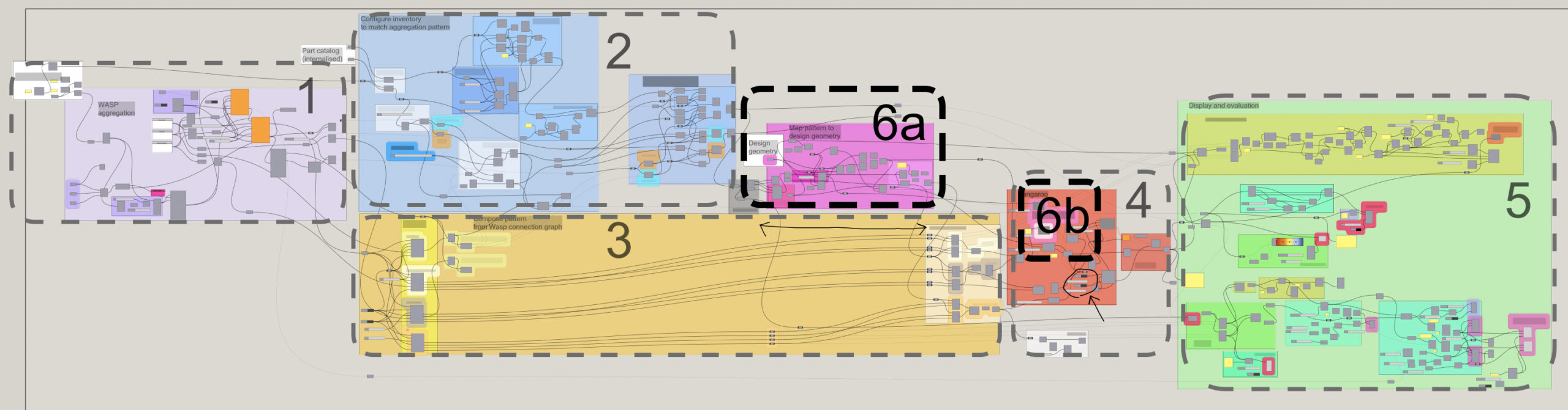
The definition is structured into 6 sections:
- Wasp aggregation
- Inventory sorting
- Part placement
- Kangaroo simulation
- Postproduction, evaluation, and labeling
- Overall design control
Basically what happens in the script is bicycle frames are first aggregated inside a bounding volume following a periodic pattern (sections 1-3) and then projected onto a design geometry (section 6).
This manual only explains section 6, for sections 1-5 please refer to the manual for bike-frame pattern 4.
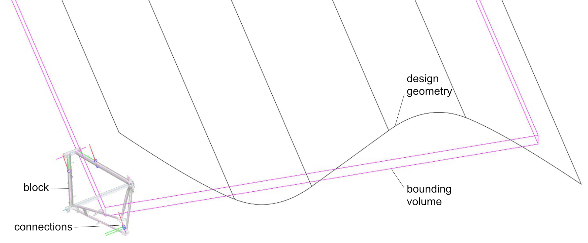
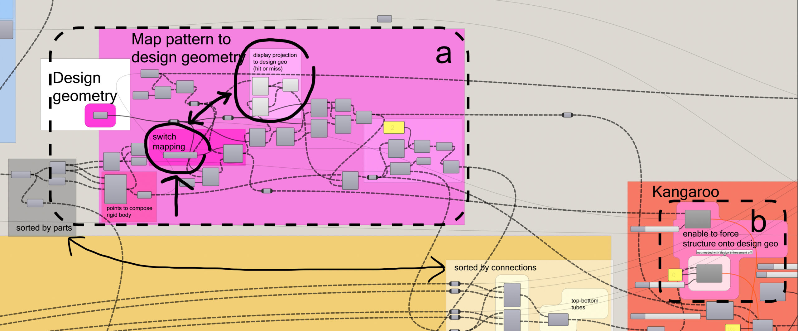
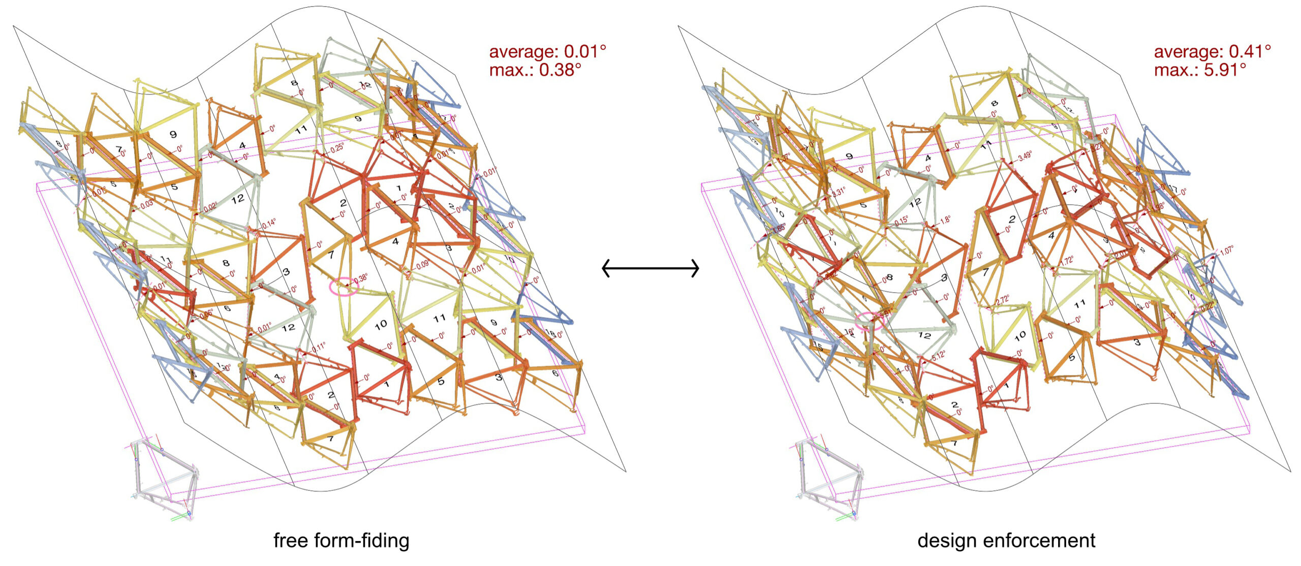
In section a at the left inside the white box “Design geometry”, a Brep (poly-surface) can be set from the Rhino workspace. When opening the definition, a Brep from the Rhino layer “waves” is set. Using the center point of each bicycle frame as reference, part instances are mapped onto the design geometry. With the highlighted component in the pink box you can switch between two modes of projection: vertical projection along the world z-vector, or closest point on surface. The highlighted components above, inside the light-pink box display the translation from the initial flat wasp aggregation (image below, left) to the projection on the design geometry (image below, right) as lines and points.
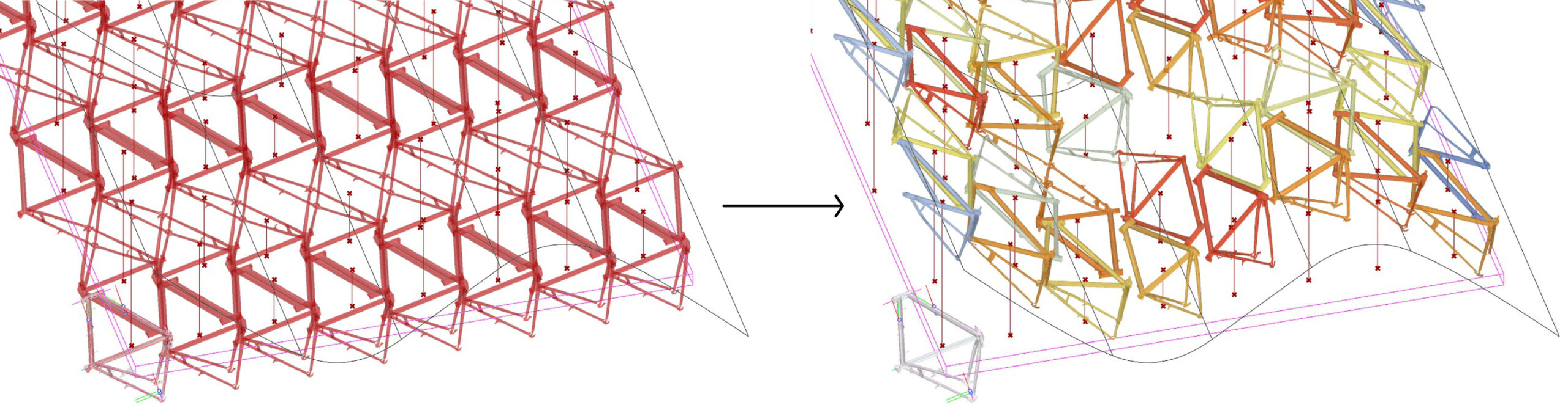
In section b, additional force constraints are added to the Kangaroo simulation (section 4) to control how the bike frame structure is forced to stay at the reference geometry. With both components disabled, the structure can freely deform in the alignment simulation, deviate from the design surface and find its own form variation with optimal connection alignment (image below, left). With both components enabled, the structure is pulled to the design geometry whilst the Kangaroo simulation is running (image below, right). This additional design enforcement however, further deforms the pattern and results in greater misalignment at the connections. Using the attached sliders, you can manipulate the strength of these constraints.
At the component inside the white box “Design geometry” at the beginning of section a, you can replace the reference geometry for mapping the bike frame structure. Inside the Rhino file in the layer “guide-src” there are a few templates for testing. To change geometry, make sure the Kangaroo simulation is disabled (boolean toggle set to false), then right-klick on the the component for design geometry – select “set Brep” and pick a geometry from the Rhino canvas. Before starting the Kangaroo simulation, klick the reset button.
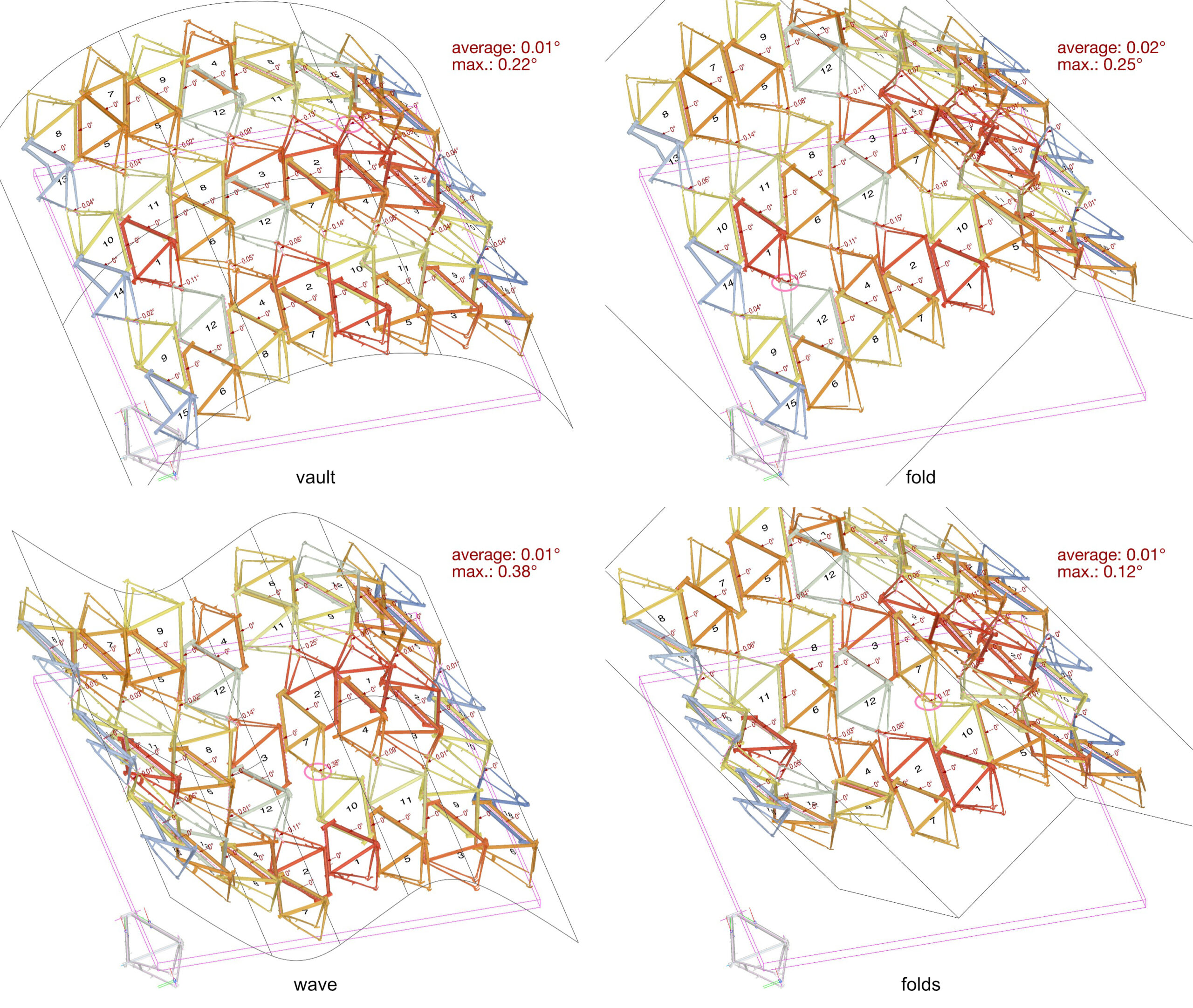
When you play with different forms, make sure the projection of parts from the initial wasp aggregation hit the design surface. You may need to change the Wasp bounding volume to adapt to a specific design.