In this study, we explore how to create a simple connection system between the detergent-bottle nodes and PVC pipes. The aim is to develop a connector system that:
- uses as few components as possible,
- can be assembled and disassembled without tools or skills,
- performs well under tension and compression,
- and reuses an existing element of the bottle (the cap).
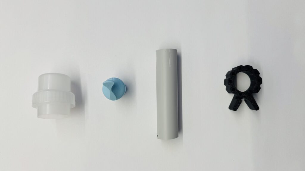
The resulting system consists of 4 components. While alternative versions for each part exist, we chose this combination because all additional parts are 3D-printed, reusable, easy to manufacture, and enable tool-free assembly and disassembly.
- cap of the detergent bottle,
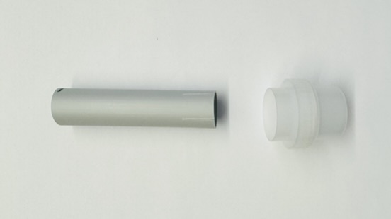
- PVC pipe (⌀ 25mm),
- 3D printed plug/ cone
- 3D printed barbell collar
In the following sections, we take a closer look at each component, their adjustable parameters, and have a look at how these parameters influence stability, usability, and reusability.
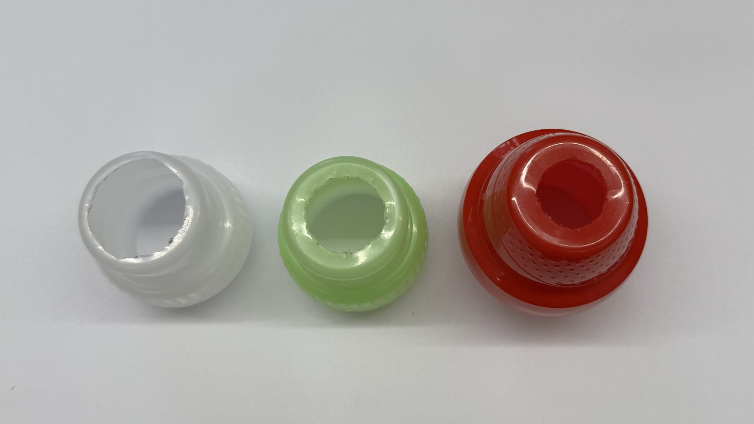
CAPS
Each cap is modified with a single central hole.
This hole defines how tightly the pipe sits inside the cap.
Parameters which can vary:
- Diameter of the drilled hole:
The hole should match the pipe’s outer diameter. We can experiment with:- a tight fit,
- or a slightly larger diameter: allows for more flexibility, enabling controlled rotation or slight movement around the joint.
This is the only main parameter on the cap itself.
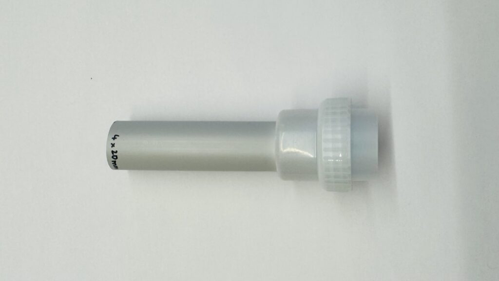
PIPES CUTES
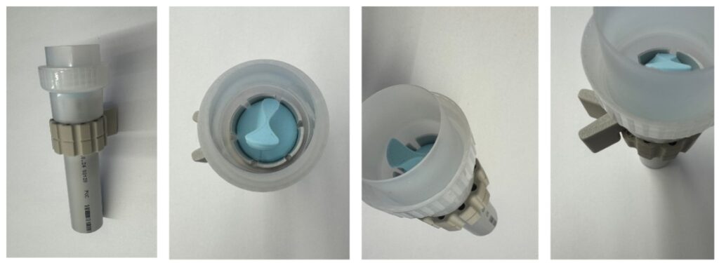
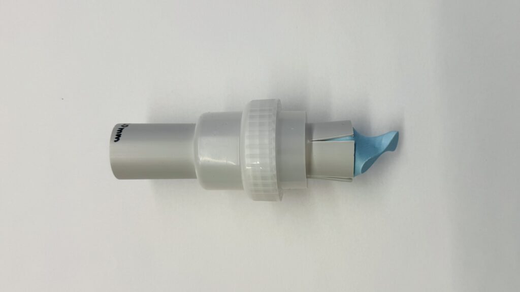
To secure the pipe under tension, the pipe is inserted through the drilled hole in the cap.
Multiple cuts are made at the pipe end and a 3D-printed cone is then inserted into these cuts, preventing the pipe from sliding back through the cap.
Adjustable parameters
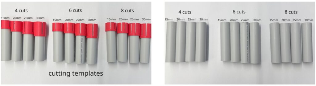
- Number of cuts (4,6 or 8)
- Length of each cut (15, 20, 25 or 30mm)
The goal:
minimal cuts and effort as much as possible while still achieving a strong and reliable hold. (We’ve developed a 3D-printed cutting template that simplifies and speeds up the cutting process. Simply place it on the end of the pipe and cut, there’s no need for measuring or marking)
3D printed cone
The 3D-printed plug/cone is the counterpart to the pipe cuts.
Its geometry determines how effectively the pipe is locked in place.
Primary parameters
- Top Diameter (26 or 30mm)
- Angle of the cone (influences how the cuts open) (5, 7.5, 10, 12.5 or 15 degree)
- Hight of the cone (20,26 or 25,30)
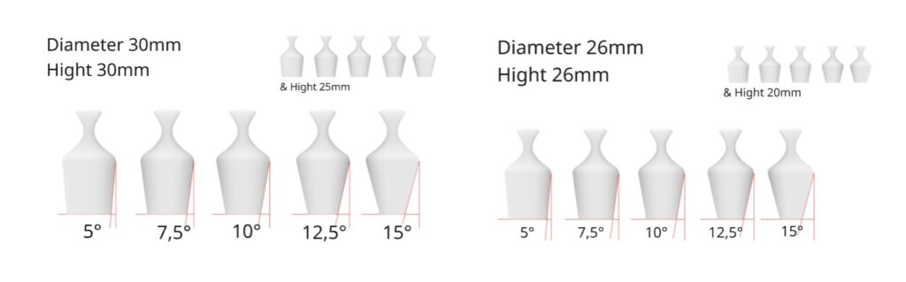
These parameters directly affect:
- tightness,
- stability,
- deformation behavior
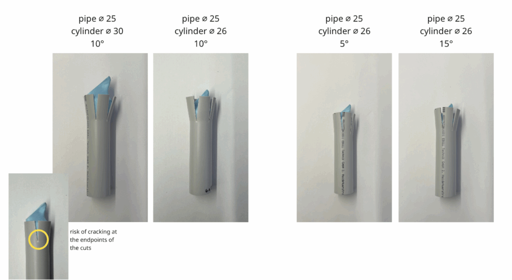
In the photo, we see different ways the cylinder deforms the pipe cuts. With fewer cuts, the openings remain straighter and more rigid. With more cuts, the individual segments become narrower and therefore bend more smoothly toward the cylinder.
The angle of the plug (its conical tip) also influences how much the cuts open. A steeper cone angle forces the cuts to open wider when the cone is inserted. The endpoints of the cuts act as stress-concentration zones. If too much pressure is applied, there is a risk of cracking at the cut endpoints, where the material is most vulnerable.
There are also secondary parameters, such as:
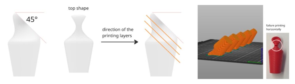
- The shape of the top surface of the cone:
This can be modified to make removal easier after disassembly and to allow the cone to be reused. - 3D-printing layer direction:
This is important for ensuring that the cone does not crack and can withstand repeated use. It’s best if the layers are oriented vertically, or at least angled at 45 degrees (not horizontally to the pull direction). (Here’s a video from CNC Kitchen that explains how print orientation affects the strength of 3D-printed parts)
To avoid using support material when printing the cylinder, design the top surface with a 45-degree chamfer. This allows direct printing at a 45° angle on that surface.
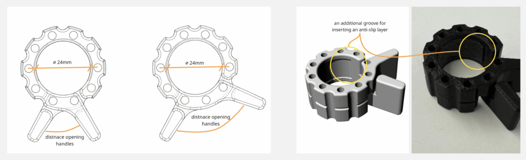
BARBELL COLLAR
The 3D-printed barbell collar prevents the pipe from being pushed deeper into the bottle when the system is under compression. It provides a stop while remaining reusable and easy to attach or remove by hand.
Parameters
- Inner diameter – must match the pipe for an effective stop.
- Thickness – influences stiffness and long-term durability.
- Shape of the outer and inner profile – affects grip, handling, and printing efficiency.
- Distance between the opening handles – defines how far the collar can open and how easily it clips onto the pipe.
- Optional friction layer – an additional anti-slip insert can improve grip.
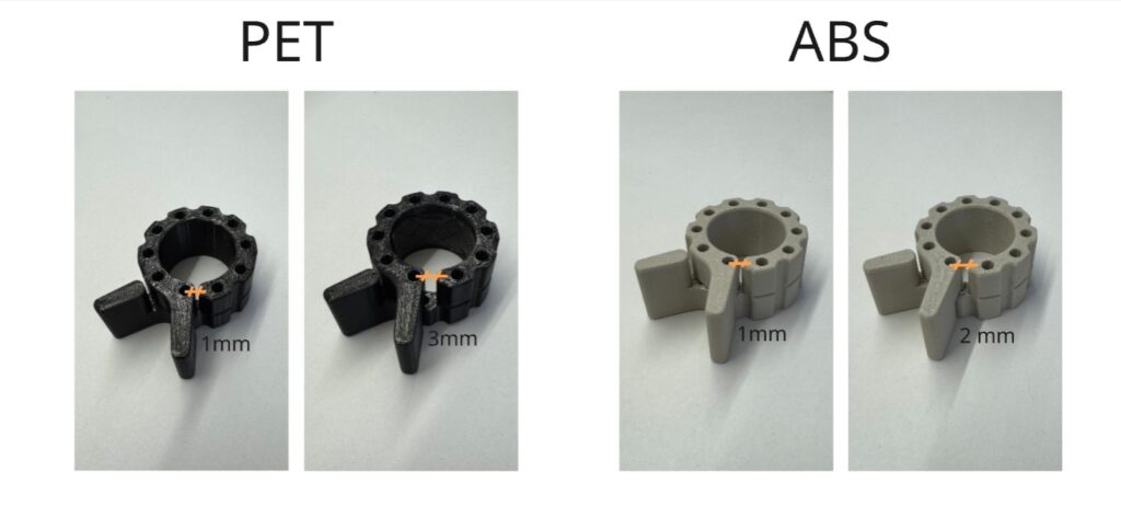
Long-Term Considerations
3D printed barbell collars can deform or lose clamping strength. For this reason, we monitor:
- how much the material opens or weakens over time,
- which printing materials provide better long-term durability (PLA, PET, and ABS were compared; ABS showed the best performance, especially after remaining clamped on the pipe for two weeks).
An alternative way to prevent the pipe from sliding would be to drill a hole through the pipe and fix it with a screw. However, we decided against this solution.
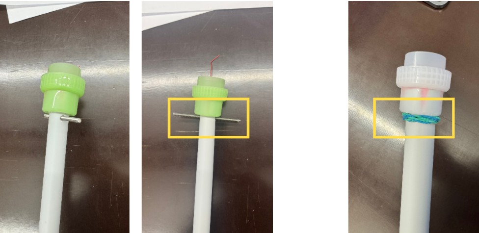
The 3D-printed barbell collar offers advantages:
- it does not require modifying the pipe itself,
- it is fully reusable,
- and it provides the flexibility to adjust its position freely during assembly, without committing to a fixed point.
The next step is to test the system at larger scales and under real conditions, evaluating how these parameters perform in full assemblies and how the connector behaves over repeated use.