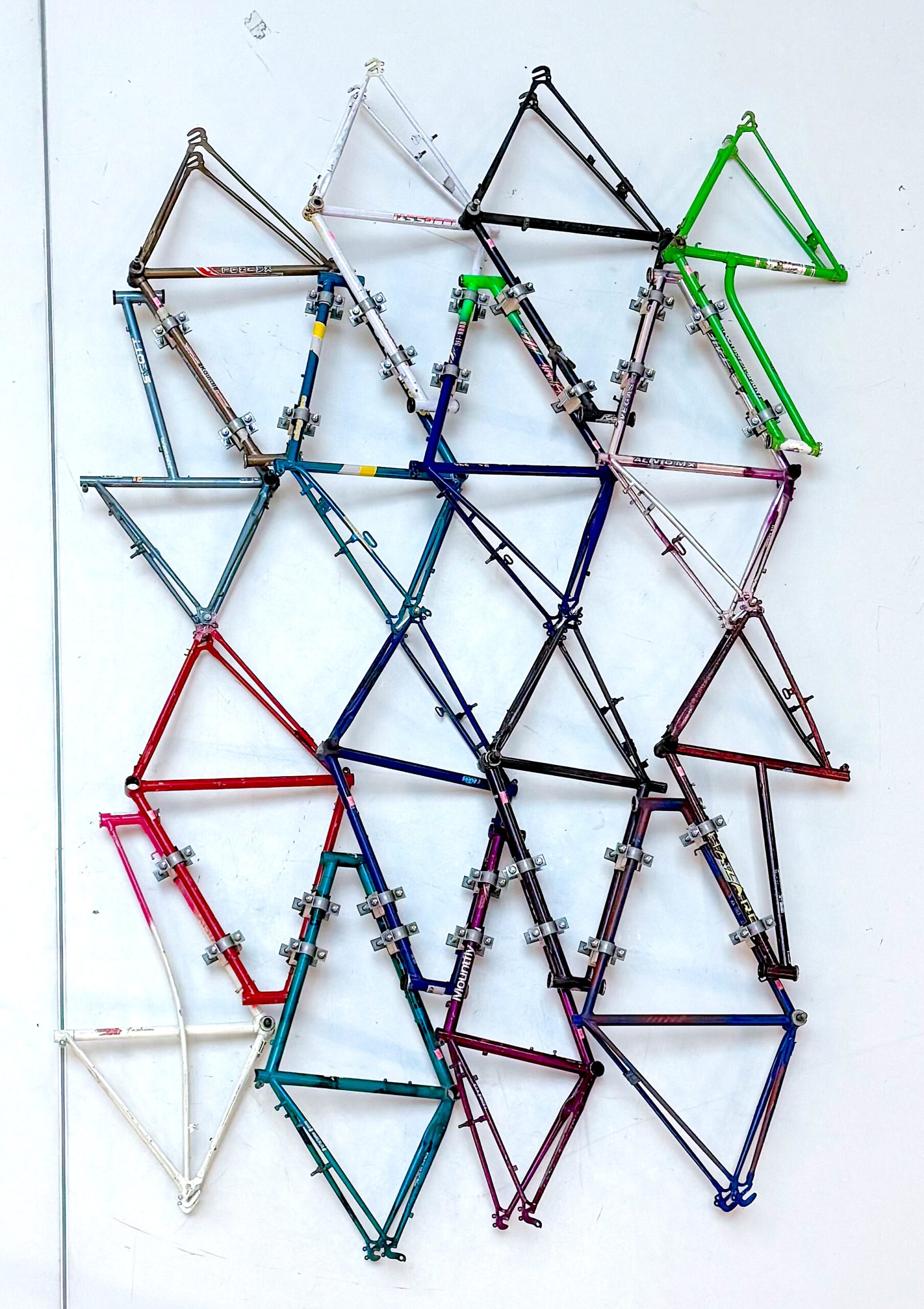
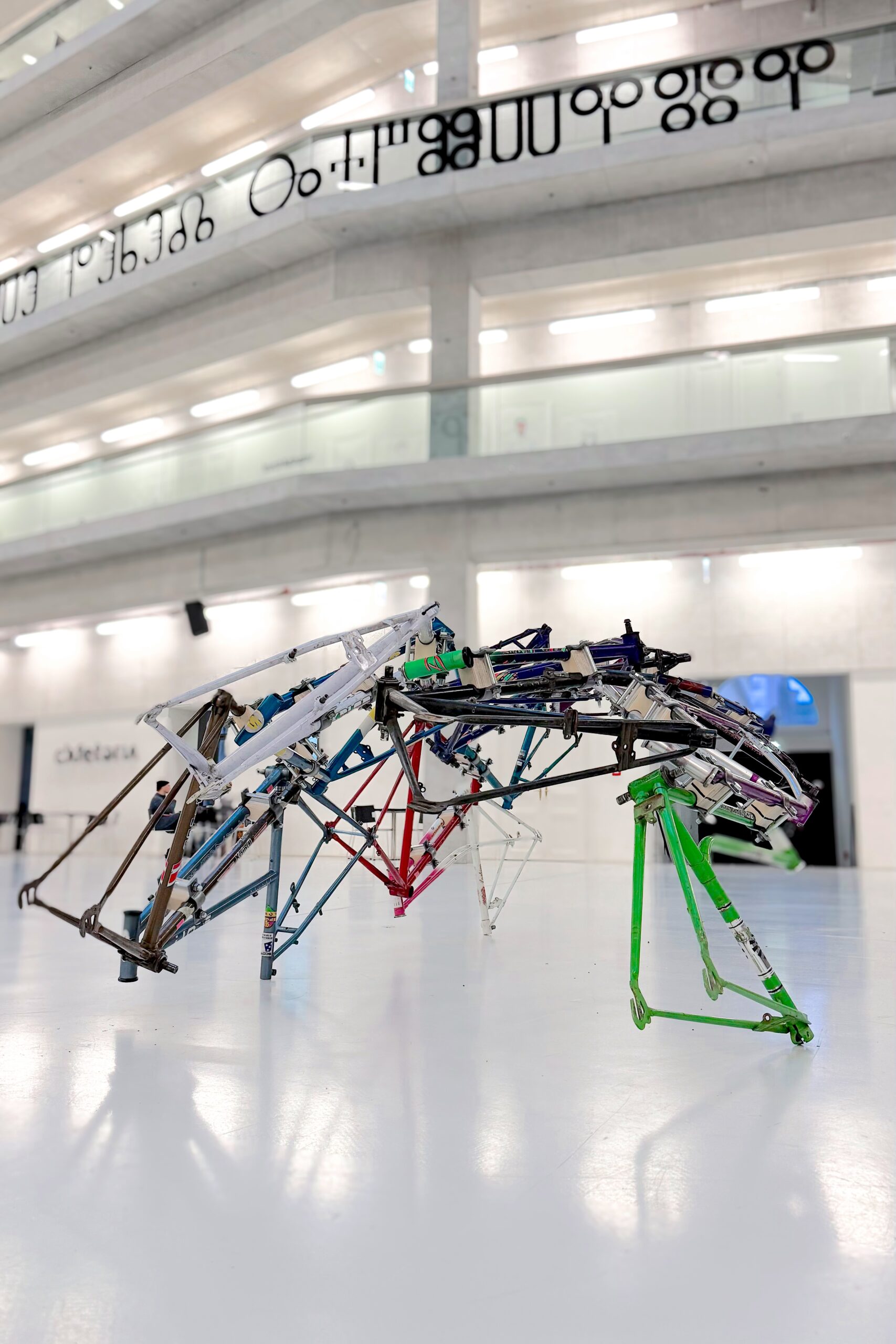
We tested a structure of 16 bicycle frames.
Based on the previously developed adaptable pattern (link) for a digital aggregation of 3d scans, we assembled the physical twins of those bicycle frames using standard connectors.

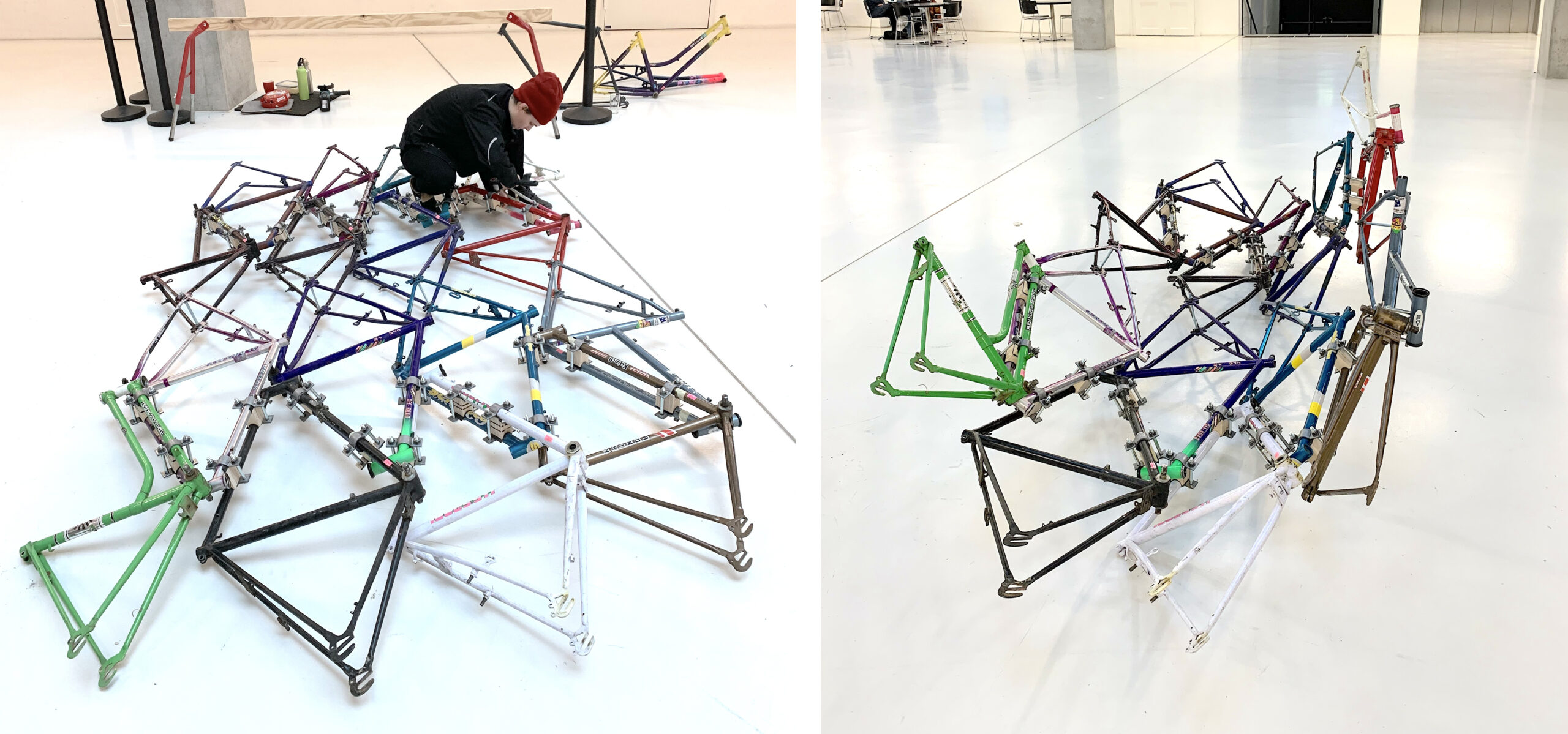
After placing the frames on the floor according to the 3D model, we marked overlaps for each connection before assembling the flat structure step by step.


Two types of connections are used, threaded rods join frames at the rear (type 1, left), and pipe fixation collars (generously sponsored by Walraven) with plywood spacers join top, and bottom pipes of adjacent frames (type 2, right). Because parts can be rotated around connection axes, and the second type can also be shifted along axes, it is possible to adapt to a wide range of frame constellations and still interconnect parts.

After tightening all connections, the mesh becomes a stiff panel. To test its capacity we put it on two linear supports along each shorter edge.


Even with its small structural height, the structure remains surprisingly stiff under load.

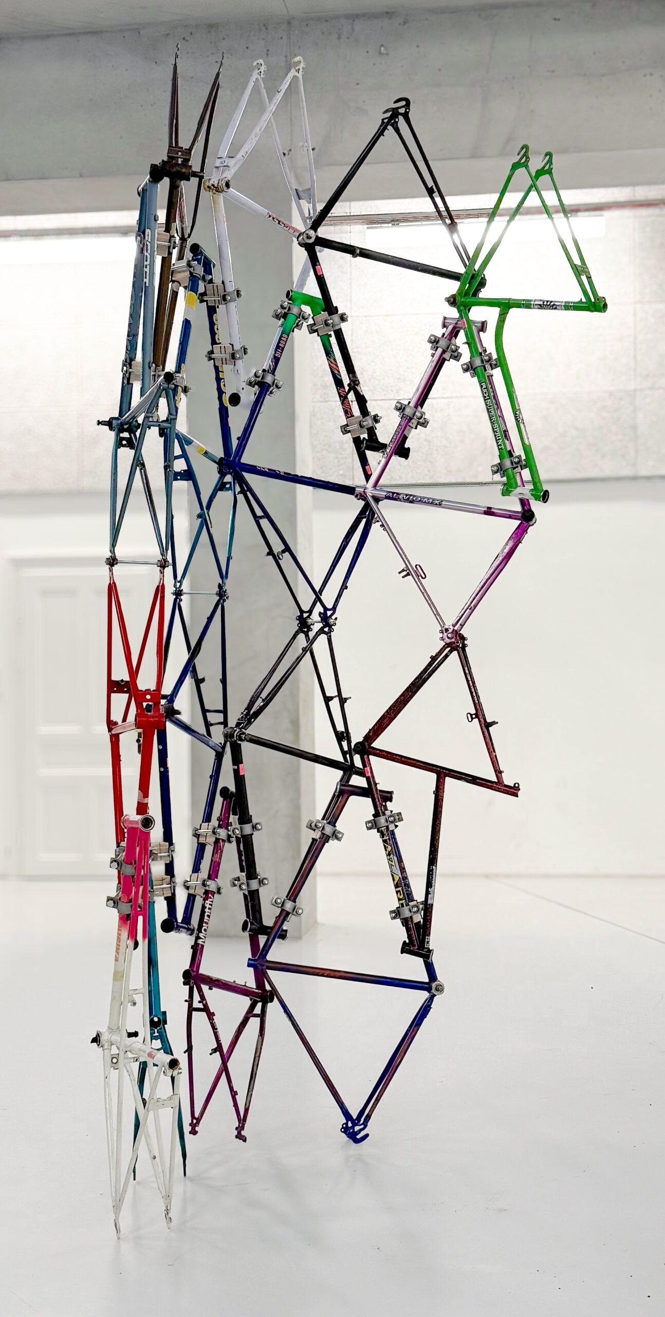
In the other direction, however as we had already seen in the previous digital studies, the structure can be bent or shaped. In longitudinal direction, the pipe collar fixed connections (type 2) act as hinges, allowing some degree of folding at each connection.
We used the same constellation of bicycle frames, loosened all connections and incrementally folded each connection a little bit without bending the parts themselves, before tightening all connectors again. The result was a curved configuration with similar stability as the flat state.


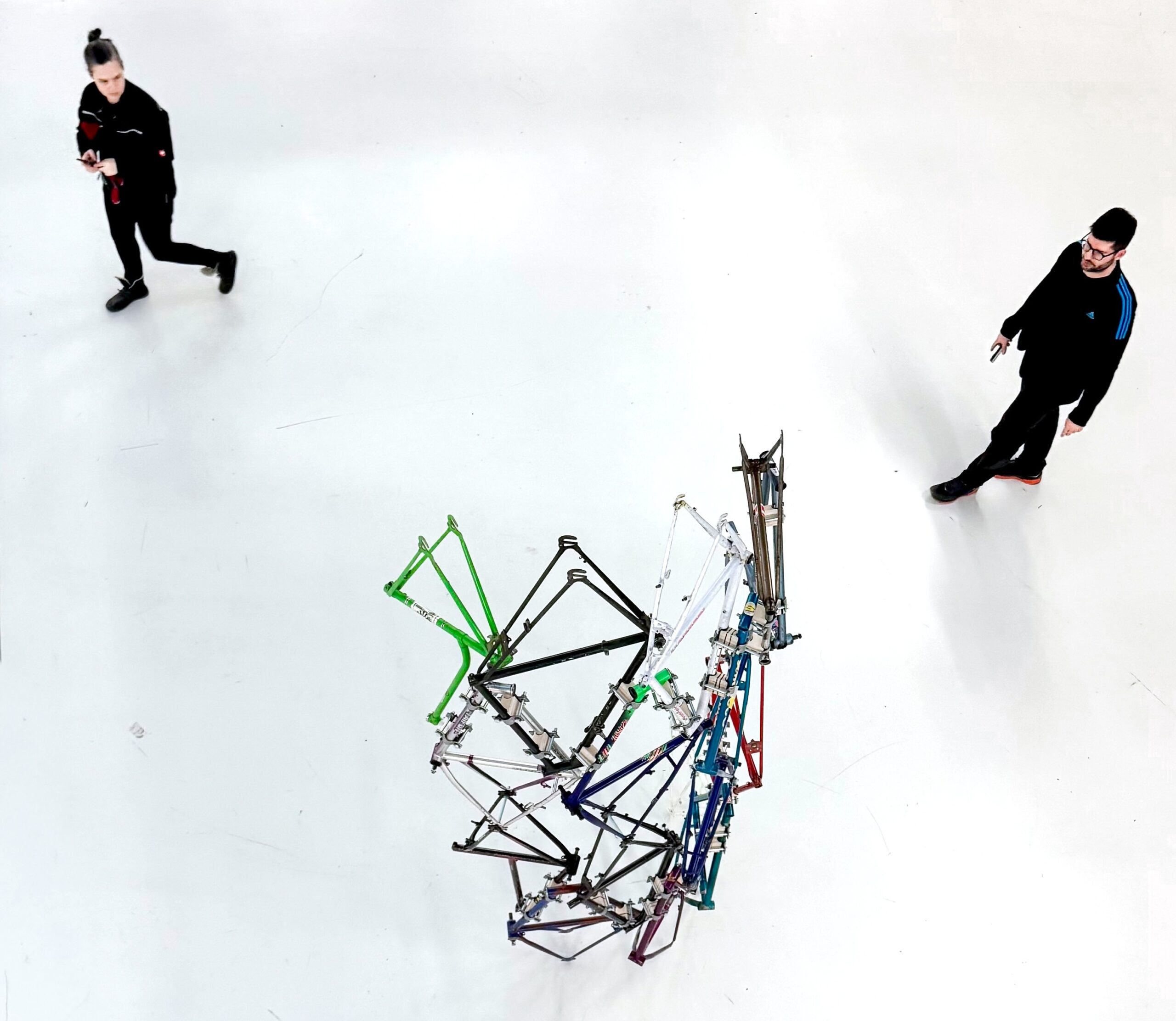
With its curved geometry, the structure has a greater stiffness than the flat panel. It can be put up vertically without additional support. Of course it is just in balance and can easily be tilted over, but with some fixation or foundations, a structure like this could become some kind of facade construction.


In horizontal orientation, the structure can bear it’s own weight, but the hinge mechanism at the joints that allowed the curved shape, prevents load bearing when put on the long edges as in the image above.
But when supports follow the curved profile along the short edge, the structure becomes stable and load bearing. In our test, the elevated bars the structure was put on were the weak part, also the improvised supports could be improved, but the structure itself remained strong.